Common Routing Errors
I will add more of these as I remember them.
This is not an exhaustive list! There are errors you can make that I am not yet aware of. This is just a list of errors I can remember and instructions on how to avoid them. When in doubt, ask Michael or one of the TAs! Sometimes you need to do something kind of bad to avoid doing something worse, and thats ok.
Additionally, many of these are subjective, and this guide represents only my opinion, not the opinion of the lecturer. When in doubt, ask them.
There are two guiding principles for routing, almost all errors are violating one of these. All tracks should be neat and as short as possible.
We want them to be neat for aesthetic reasons, but we want them to be as short as possible because the longer a track is, the more resistance it has. We can see this from the formula for resistance: \[ R = \rho \frac{L}{A} \] Where:
- \(\rho\) is the “resistivity” of the material
- \(L\) is the length of the wire
- \(A\) is the area of the wire
Because \(R \propto L\) (\(R\) is proportional to \(L\)), if we double the length of the wire, we double its resistance. Because of this, we try to keep any power tracks as short as possible.
For example, in project one we have power lines that can draw as much as \(300mA\). This means that if have a power track with a resistance of \(1 \Omega\) we get a voltage drop across it of \(300 mV\).
Therefore, with power lines (such as +5V and GND), we want to keep them as short as possible to minimise resistance.
Functional Guidelines
These are guidelines that affect the functionality of the board.
Long Tracks
This one matters more for power wires because the voltage drop across a wire is proportional to current. For most signal lines the current through them is extremely low, so the resistance doesn’t matter too much.
Generally shorter lines are more efficient, but prioritise making power lines shorter even if that means using a longer signal line.
Right Angles
Right angle traces are generally frowned upon. This is because if you have a right angle, generally speaking you can get a shorter path by taking a diagonal path.
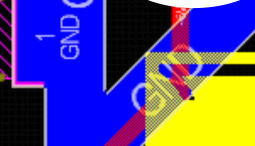
One exception to this is junctions. We prefer a T junction over something like this:
1 All images taken from the week 2 slides on canvas.
Unnecessary Vias
For both project one and project two you will have a limit to the number of vias you can use. Avoid using them unnecessarily, for example:
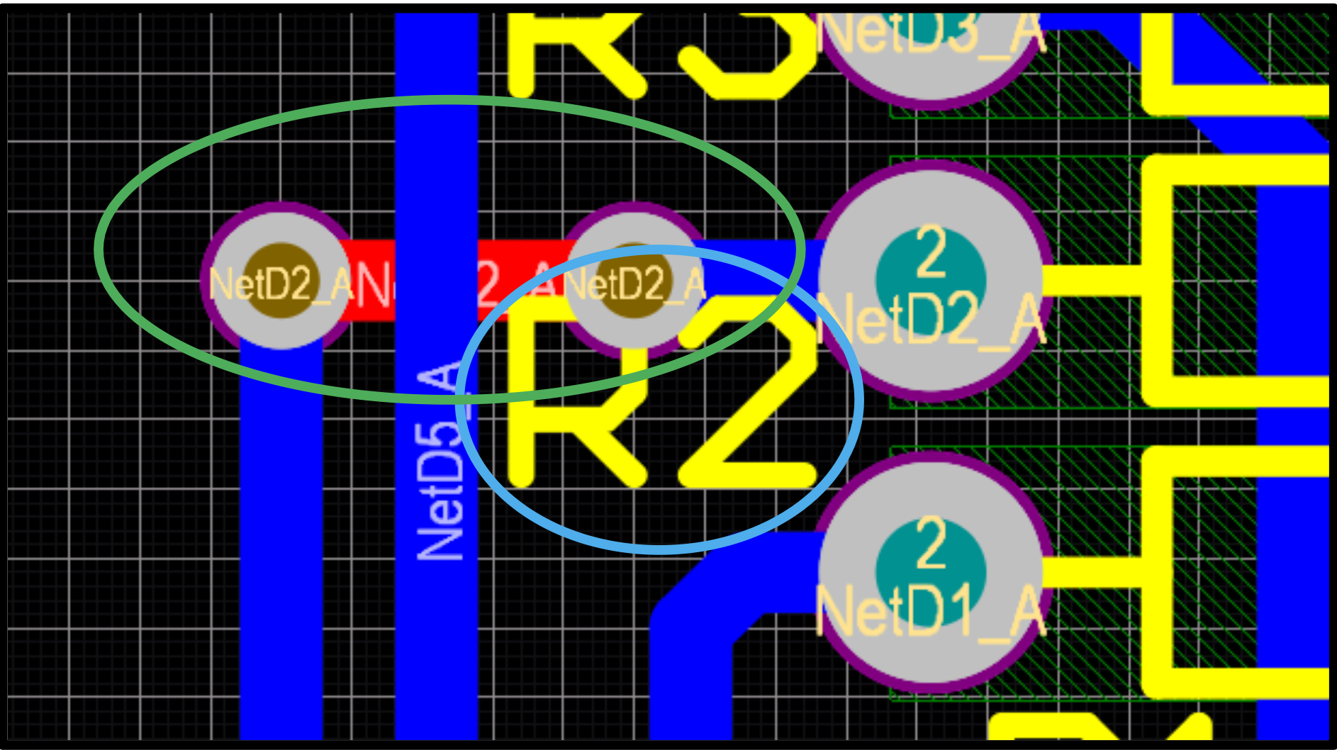
Only one of the vias in the green circle is necessary as the diode on the right is a through hole component, and as such the top layer track (red) can connect to it directly.
Aesthetic Guidelines
These are guidelines that are entirely aesthetic preferences. If you violate these you will probably receive a lower grade, but they shouldn’t affect how functional your board is.
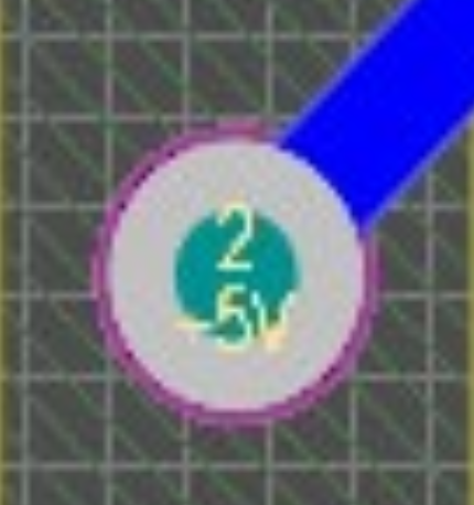
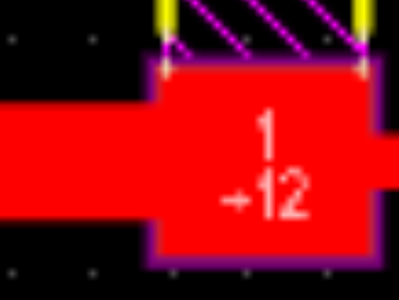
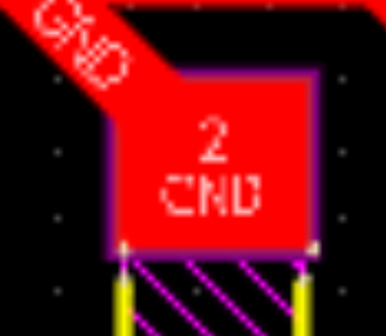
45 Degree Pad Connections on Square Pads
With circular pads you can connect to it at either right angles or 45 degree angles, but with square pads you should only connect to it on one of the flat sides.