Project Two Assembly Guide
Overview
This project is about as difficult as Project One, just with more components.
What is refered to as the Top Layer will actually end up facing down when it is fully assembled. The Top Layer has more SMD components than the Bottom Layer, so you should solder that with the Pick-&-Place machine.
Drilling out the slots
As shown with the mechanical drawing on canvas, you will need to drill out some slots in the box you are given.
I recommend covering the outside of your board with masking tape, and drawing the correct locations of your slots in pencil on that masking tape.
To cut the slots themselves, use the drill press to drill holes around the inside edge of the slot, and then use the files to smooth the edges out like so:
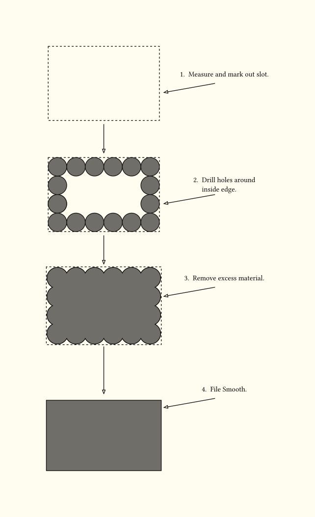
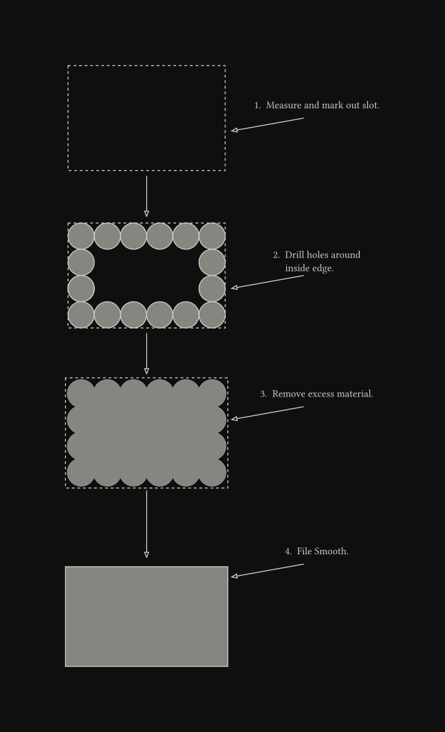
THESE ARE DRILL BITS, NOT ENDMILLS.
DO NOT DRILL INTO YOUR BOX AND MOVE IT AROUND.
YOU WILL BREAK THE DRILL BIT.
Acrylic Bending
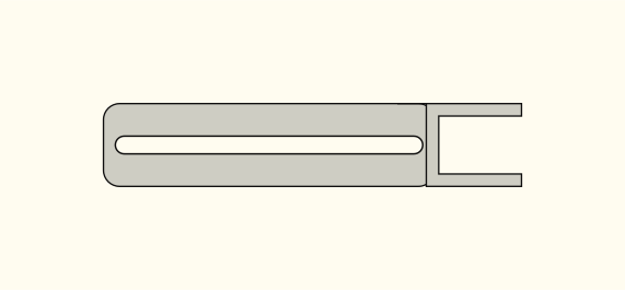
To bend the acrylic, use the acrylic bending station to heat the bend lines as shown here:
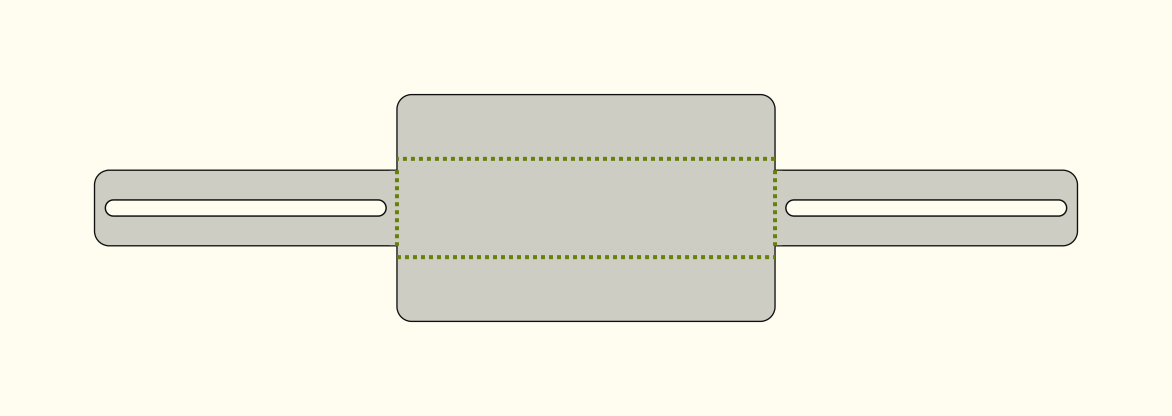
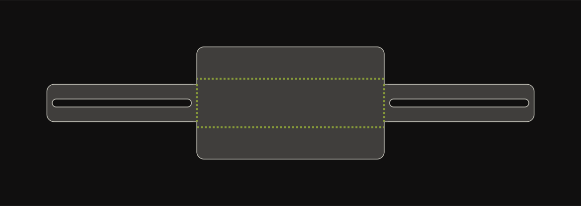
The side flaps should be bent the opposite direction to the top and bottom flaps. When its done, it should look like this from the side:

Components
SMD Components — 35 parts
| Designator | Comment | Description | Side | Qty | Code | Bin # |
|---|---|---|---|---|---|---|
C6 C9 C11 |
0.1uF | SMD capacitor | Top | 3 | - | 25 |
C7 C12 |
4.7uF | SMD capacitor | Top | 2 | - | 24 |
C10 |
10nF | SMD capacitor | Top | 1 | - | 9 |
D9 D10 D11 |
- | Schottky rectifier | Top | 3 | - | 27 |
R14 |
330R | SMD resistor | Top | 1 | 331 |
22 |
R5 R6 |
2k2 | SMD resistor | Top | 2 | 222 |
19 |
R7 R10 R20 |
10k | SMD resistor | Top | 3 | 103 |
3 |
R8 R17 R18 |
1k | SMD resistor | Top | 3 | 102 |
11 |
R9 |
820R | SMD resistor | Top | 1 | 821 |
17 |
R11 R12 R13 |
560R | SMD resistor | Top | 3 | 561 |
16 |
R15 |
100R | SMD resistor | Top | 1 | 101 |
1 |
R19 |
8k2 | SMD resistor | Top | 1 | 822 |
14 |
U2 |
- | Decade counter | Top | 1 | - | Project Kit |
U3 |
ATTINY2313 | 8-bit AVR microcontroller | Top | 1 | - | Project Kit |
U4 |
555 Timer | General-purpose single bipolar timer | Top | 1 | - | Project Kit |
F1 |
- | PTC resettable fuse | Bottom | 1 | Project Kit | |
D3 D8 D12 |
- | Schottky rectifier | Bottom | 3 | - | 27 |
D4 D5 D16 |
- | Red LED | Bottom | 3 | - | Project Kit |
R1 R2 |
330R | SMD resistor | Bottom | 2 | 331 |
22 |
(This is assuming all resistors are using the 3 digit codes, if they are using 4 digit codes I will update this website.)
Through-Hole Components — 36 parts
| Designator | Comment | Description | Side | Qty | Bin # |
|---|---|---|---|---|---|
BC1 |
Buck | Header, 3 pin, 2.54 mm, straight | Top | 1 | 29 |
C1 |
4700uF | Polarized aluminium capacitor | Top | 1 | Project Kit |
C2 C5 C8 |
100uF | Polarized aluminium capacitor | Top | 3 | 31 |
C3 C4 |
0.1uF | Non-polarized ceramic radial capacitor | Top | 2 | 21 |
D1 D2 D6 D7 |
- | Rectifier diode | Top | 4 | 26 |
Q1 Q2 |
- | NPN bipolar transistor | Top | 2 | 28 |
R3 R4 |
1R | Through hole resistor | Top | 2 | 15 |
U1 |
- | 5 V, 2 A LDO, TO-220-3 | Top | 1 | Project Kit |
USB1 |
Battery Charger | USB Type-A receptacle | Top | 1 | Project Kit |
D13 D14 D15 |
- | 3 mm red LED, through hole | Bottom | 3 | 36 |
LS1 |
Buzzer | Buzzer | Bottom | 1 | Project Kit |
P1 |
Input Selector | Header, 2 pin dual row, 2.54 mm | Bottom | 1 | 30 |
P2 |
ISP Header | Box header, 10-way (2x5), 2.54 mm | Bottom | 1 | Project Kit |
P3 |
RST Jumper | Header, 2 pin, 2.54 mm | Bottom | 1 | 4 |
P4 |
A/D Selector | Header, 3 pin, 2.54 mm | Bottom | 1 | 29 |
R16 |
10k | Potentiometer | Bottom | 1 | Project Kit |
S1 S2 |
- | Button | Bottom | 2 | Project Kit |
TM1 TM2 TM3 TM4 |
Test points | Turret mount | Bottom | 1 | 32 |
Misc
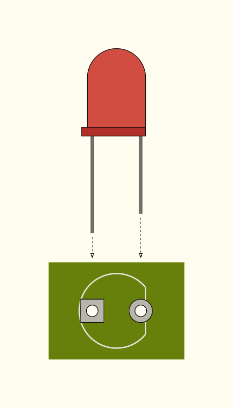
Through hole LED direction
This project has a couple of through hole LEDs.
For this project, they go in like this:
SMD diode direction
This project contains multiple SMD schottky diodes. (D3, D8, D9, D10, D11, D12) These are placed on the board like this:
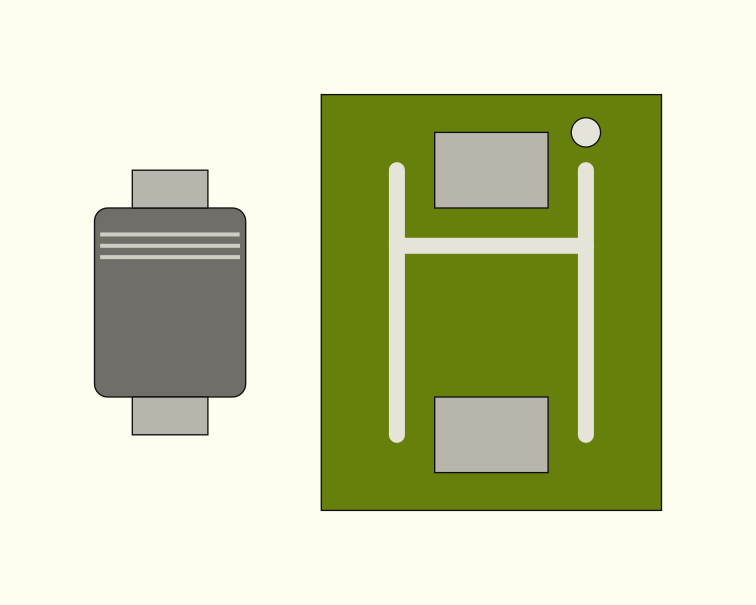
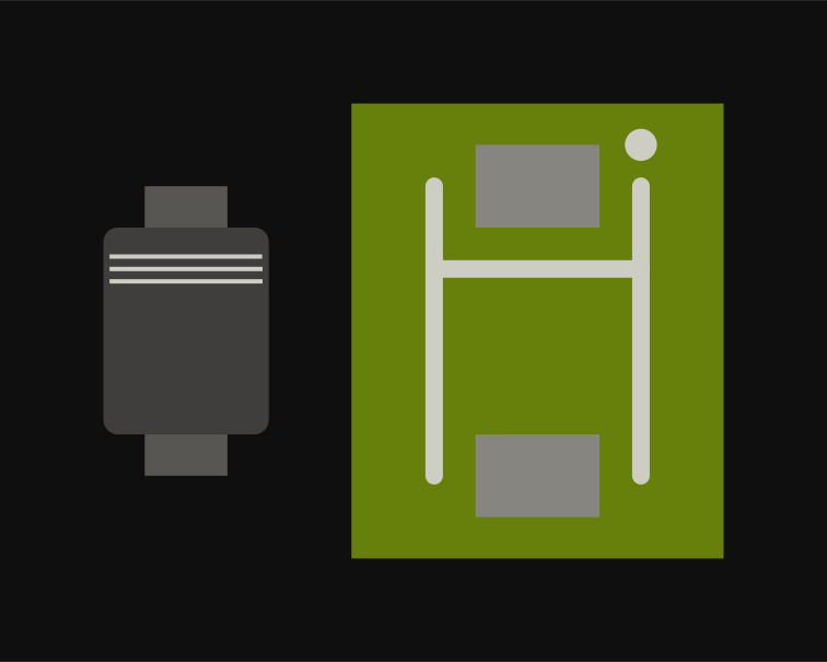
The two lines on the diode can be hard to see, use the microscope!