Project One Assembly Guide
The designators for C3 and C2 have been swapped on the PCB. We intend for the larger 4.7uF capacitor to be located on the microcontroller (U2) Vcc pin, not as a decoupling capacitor for U1
Project One Assembly Steps
1 - Cut out board using the Guillotine
Make sure you cut just slightly outside the white line.
We want it to look like this:
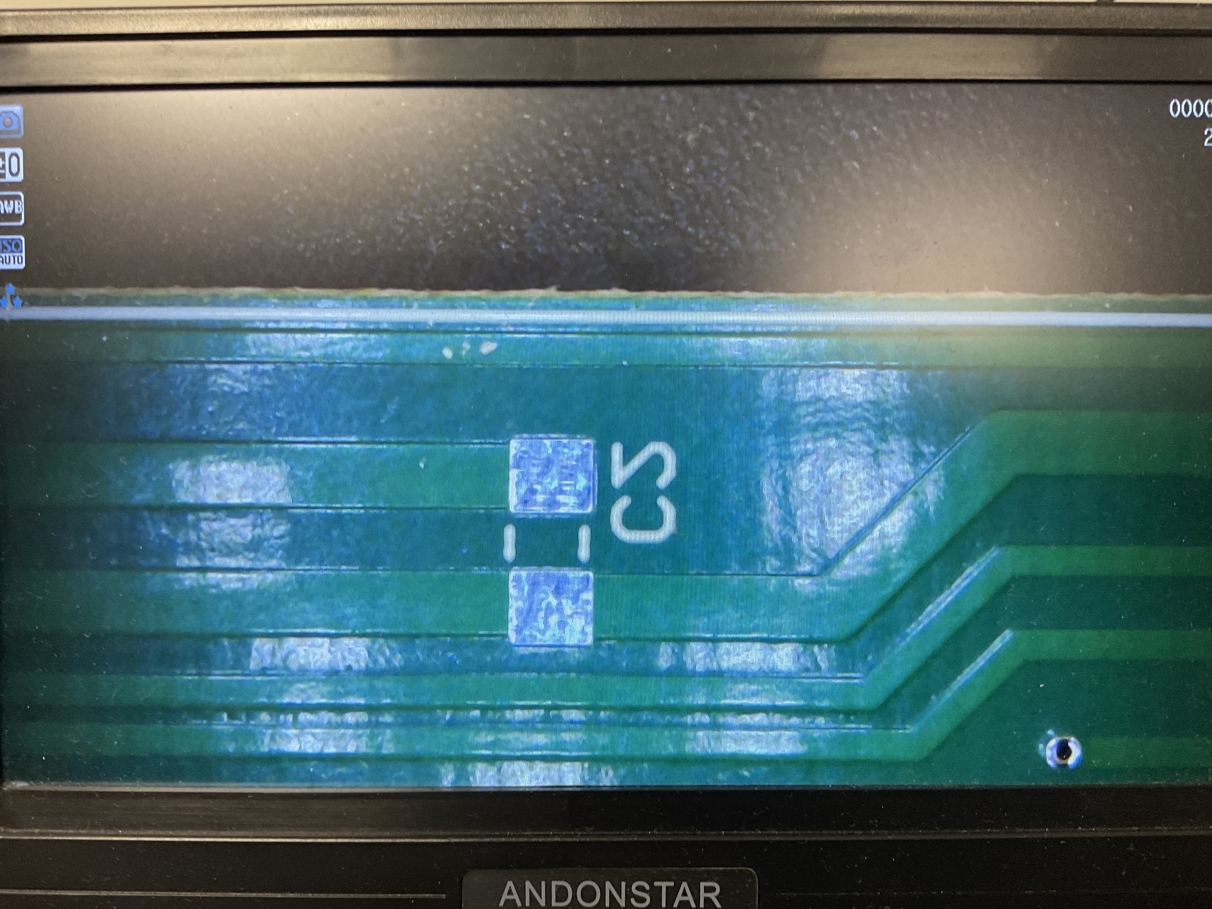
- The white line should still be on the board.
- It is better to cut off too little than too much (you can cut it a second time!)
- Try to keep the edges as straight as possible (push the board up against the left side of the guillotine)
Do not, under any circumstances, file your board edge. PCBs are made of fibreglass, and breathing that stuff in is extremely bad for you. You are putting yourself and others at risk.
2 - Soldering
Solder Bottom Layer SMD components
For this step, use the Pick & Place machine to deposit solder paste onto the pads, and then place the components
I recommend doing it in this order:
- Place solder for microcontroller pads
- Place microcontroller onto its pads
- Place solder for other pads
- Place other components on their pads.
You should do it this way because the microcontroller is very easy to mess up, and doing it in this order minimises the work required to retry if you smear solder paste around.
Reflow Board in Oven
- Make sure the temperature curve is set to
WAVE 2. - Place board in oven.
- Press “Execute Temperature Curve”
Solder top layer SMD components
For the top layer LEDs (D1, D2, and D3) you need to do these by hand.
- Melt a small amount of solder onto the pad closest to your dominant hand
- Use tweezers to hold the component on the pads 1
- Melt the solder using your soldering iron.
- Once the component is exactly where you want it, withdraw the soldering iron while still holding the component in place.
- Solder the other side.
1 I recommend using reverse tweezers for this, squeezing normal tweezers makes your hands shake more.
This takes practice! Try it on some spare boards before you do it on your actual components.
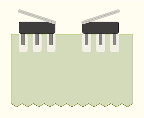
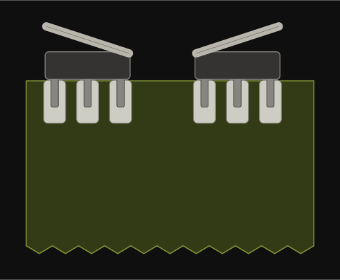
You will also need to attach the switches like this:
Solder through hole components
This includes:
- The H-Bridge (
U1) - The ISP header (
P3) - The USB port. (
USB1) - The connectors for the line following board (
P4)
Please make sure that these components are installed on the correct side of the board as they are extremely difficult to desolder. All of them go on the side with the silkscreen for that component (i.e. its designator and a little white outline for that component)
The connectors for the line following board are not symmetrical but it doesnt matter which way around they go, so long as they are both the same.
3 - Assemble Line Following Board
This is the same as the SMD soldering for the main board, and should be done using the Pick-&-Place machine, you can do this at the same time as your main board and cook them together.
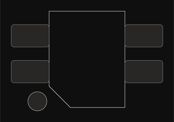
Ensure the optocouplers (line sensors) are oriented correctly. They have a chamfered corner which must match up with a dot on the board. Like this:
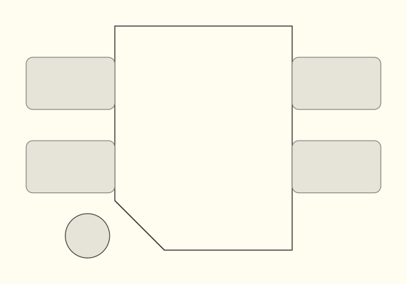
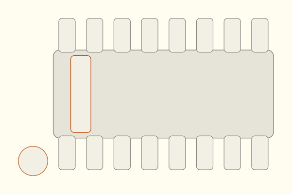
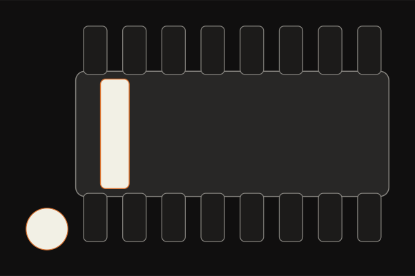
Additionally, take care to ensure your op-amp chip is oriented correctly. It should have a stripe, which will line up with a dot on the board.
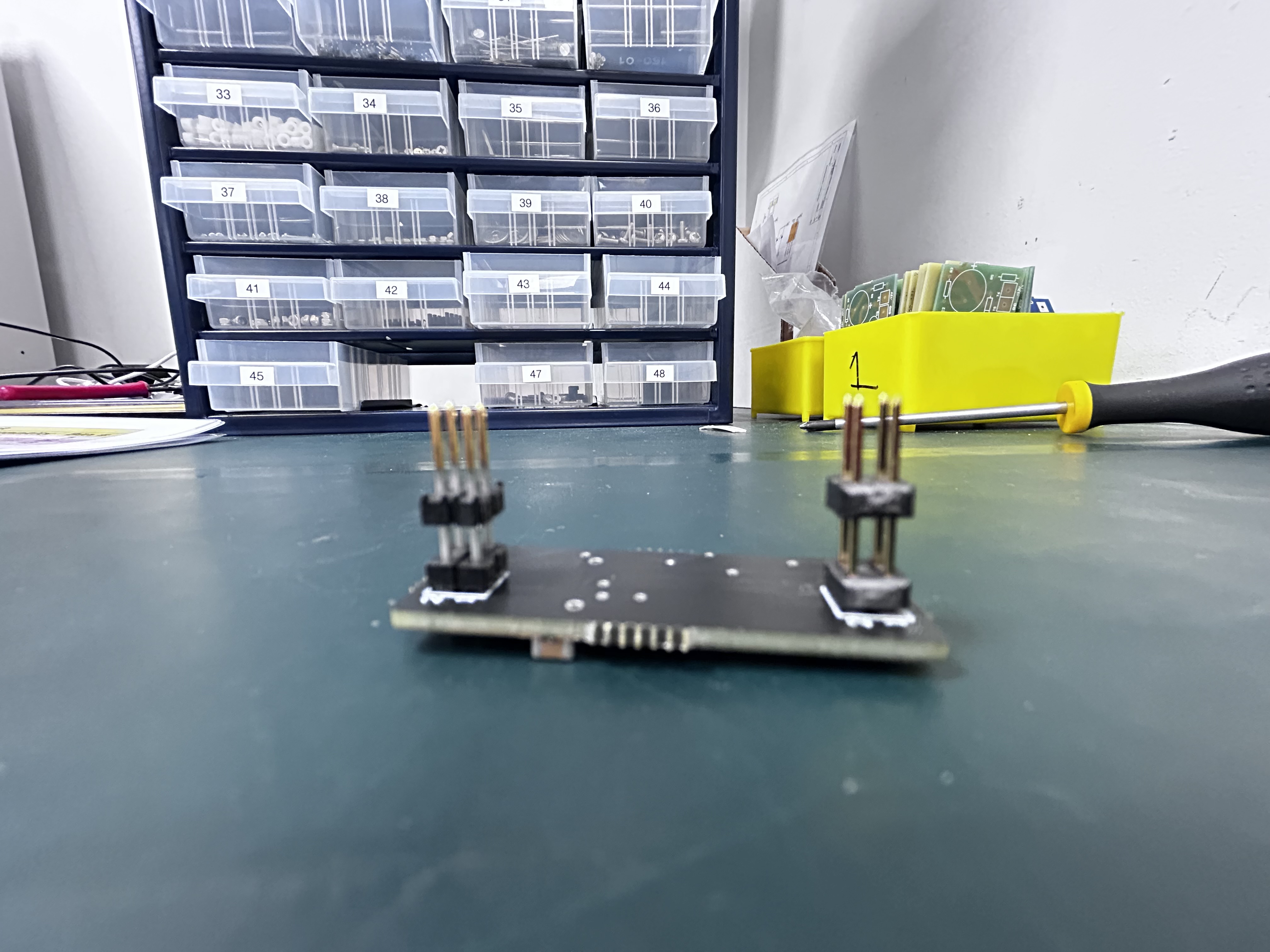
Once done with the SMD soldering, solder the long 2x2 headers to the line following board like so:
4 - Physical Assembly
Click here for the STL files for the 3D printed parts if for whatever reason you need to reprint them.
Attach motors to frame
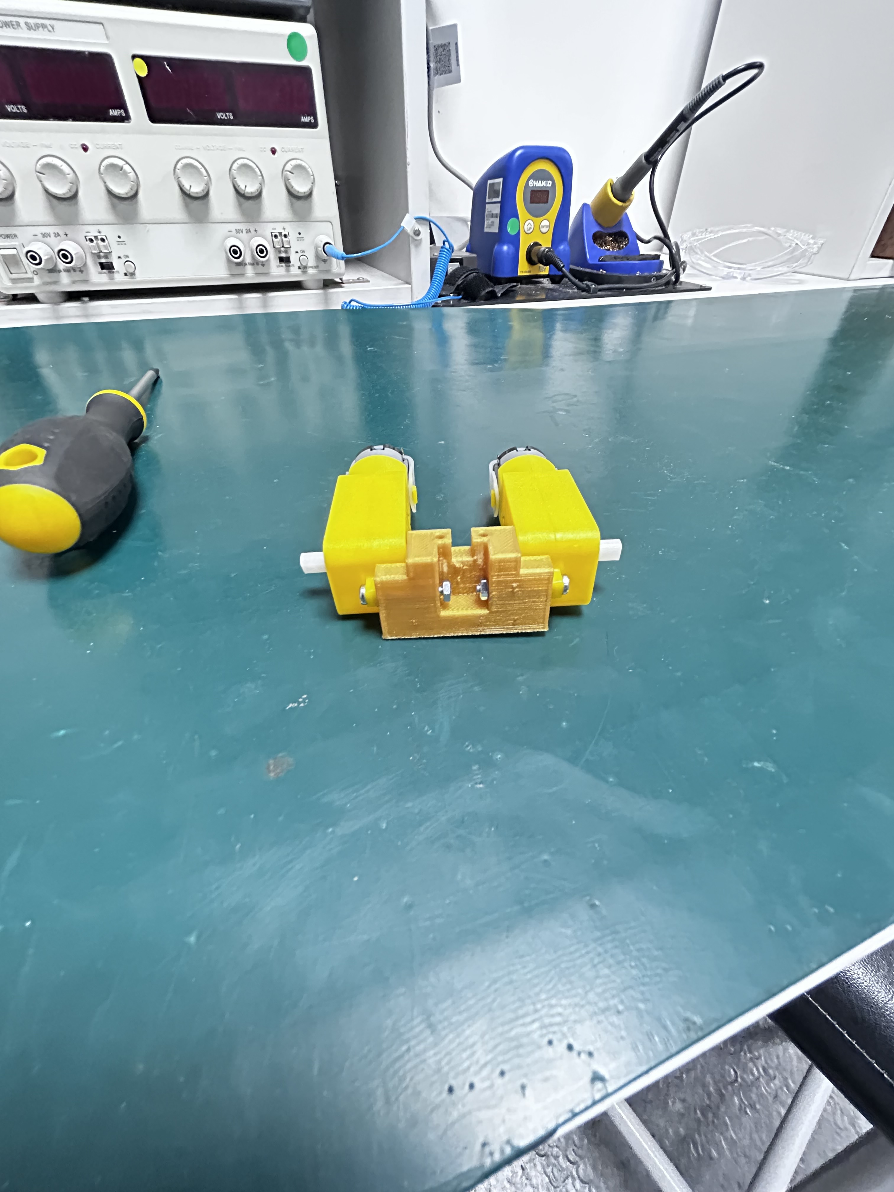
- Thread the smaller flathead screws through each motor and into the motor frame.
- Use either tweezers or pliers to hold the nut in place.
- Ensure the motor contacts are on the inside!
Attach motors to standoffs
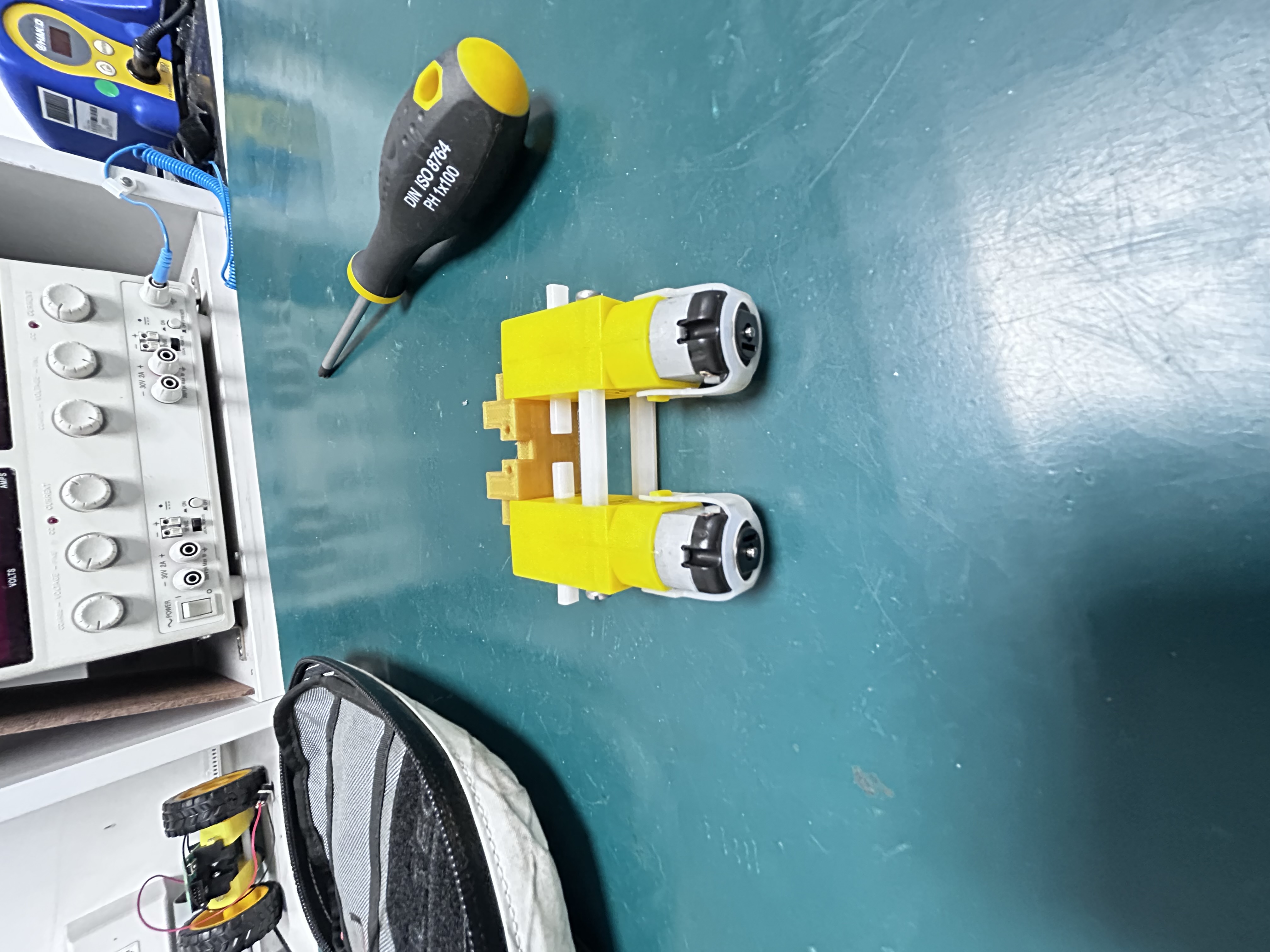
Use the larger 4 flathead screws to attach the standoffs inside the motor frame.
Attach motor frame to PCB
_ 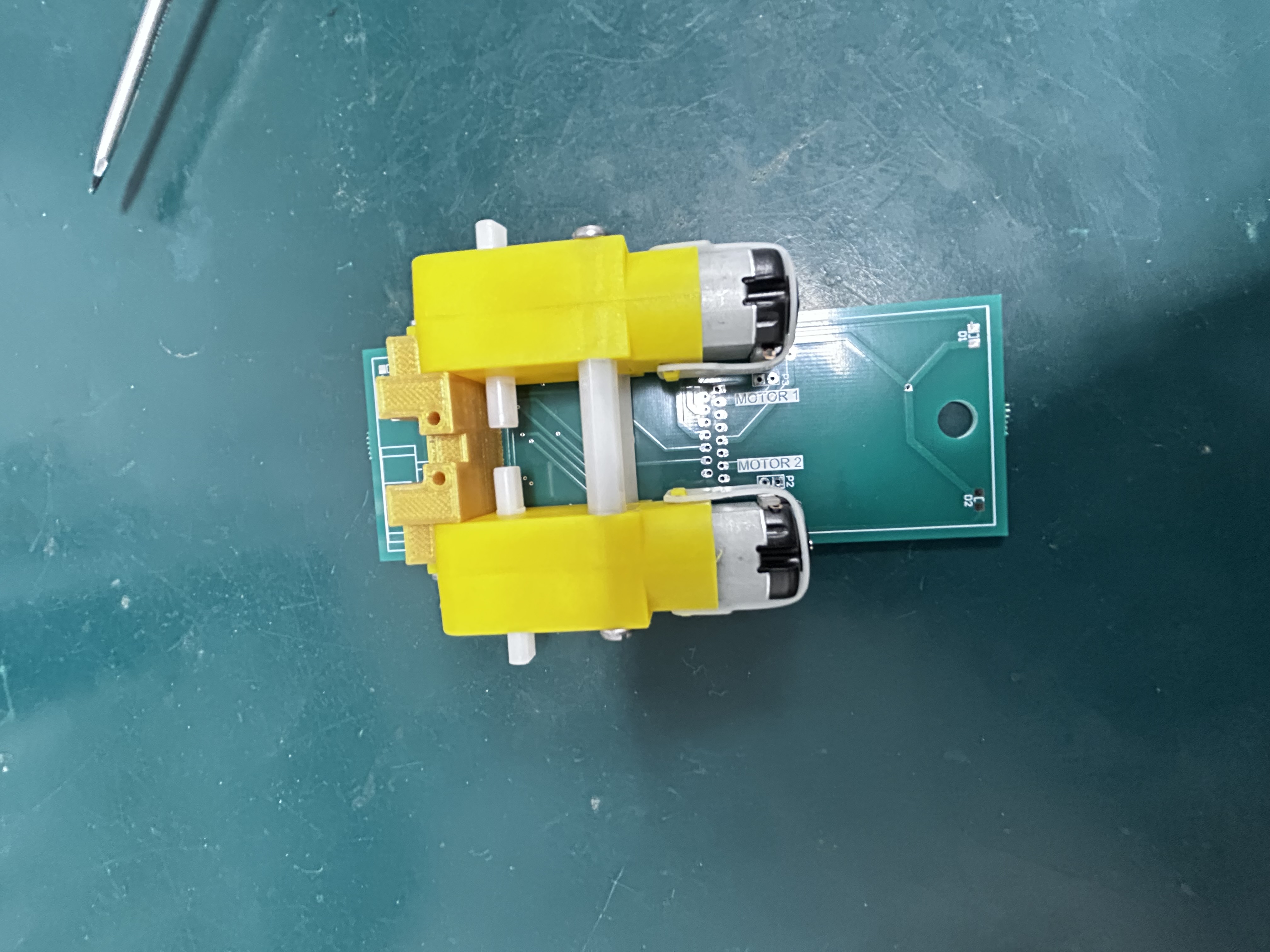
- Place the motor frame on the TOP SIDE of the board (the side with the LEDs)
- Use the self tapping screws to attach the motor frame to the PCB using the two screw holes.
- Ensure the cable channel is on the top side!
Solder wires to motors.
- Cut four lengths of multi-core wire, approximately 6-8 cm long in appropriate colours.
- For example, red for positive and black for negative.
- Strip and tin2 them.
- If the motor frame is assembled correctly, both motors have their positive contact on top. you should solder your positive wire to the top contact.
2 This means apply a small amount of solder to them to keep the strands of conductor within the wire together.
Solder wires to board
- Twist the wires together 5-8 times (the wires should be twisted together tightly)
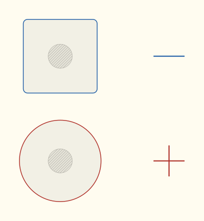
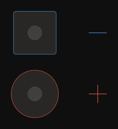
- Solder positive wires to circlular pads.
- Solder negative wires to square pads.
Attach front roller and whisker
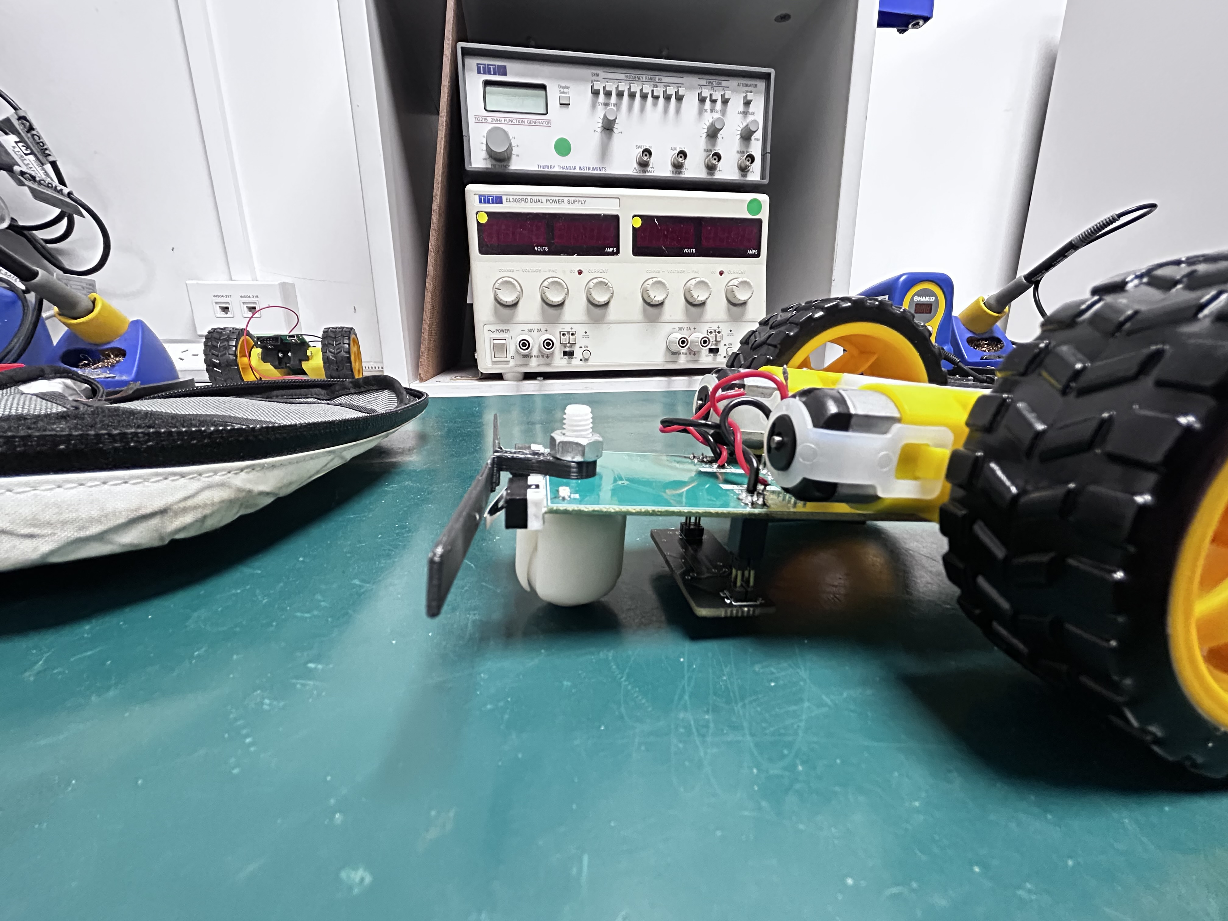
- Place the roller screw through the bottom of the board.
- Place the whisker on the screw, making sure it is in front of the switches.
- Secure the roller and whisker with the M6 nut. 3
3 For some people, you may have a roller where the metal M6 nuts do not fit, we have 3D printed special nuts for these rollers.
Like so:
Components
SMD Components
You can download this as a file by clicking this link.
Resistors
| Designators | Value | Code | Quantity | Bin # |
|---|---|---|---|---|
R1 |
22R | 22 |
1 | 43 |
R2 R3 R4 R5 |
330R | 331 |
4 | 22 |
R6 |
120R | 121 |
1 | 7 |
Use this to calculate the resistance from the code.
Capacitors
| Designators | Value | Quantity | Bin # |
|---|---|---|---|
C1 C3 |
0.1 μF | 2 | 25 |
C2 |
4.7μF | 1 | 24 |
The 4.7μF capacitor is thicker than the 0.1μF capacitors.
LEDs
| Designators | Value | Quantity |
|---|---|---|
D1 D2 D3 |
BLUE | 3 |
These come in your project kit
Integrated Circuits
| Designator | Component | Description |
|---|---|---|
U1 |
L298 | Dual H-Bridge Motor Driver |
U2 |
ATTINY1634 | Microcontroller |
Through-Hole Components
| Designator | Component | Description |
|---|---|---|
U1 |
L298HN | Motor Driver |
P3 |
05x02 Horizontal IDC header | ISP Programming Connector |
USB1 |
MINI USB Type A/B, Receptacle, Through Hole | USB Power input connector |
P4 |
2x 02x02 2.54mm box header. | Connectors for line following board. |
How to submit your robot
To submit your robot, place it in the plastic bag your project kit was in, along with a piece of paper with your name, student ID, and stream number on it. Hand it in to either a TA or Michael Bunn during a lab session.
If you are unable to hand it in during a lab session, contact Michael Bunn directly to arrange something else.